


BLOG
Discover the latest from the industry
-
Sena at Vélo in Paris 2026: Bringing Connected Cycling to Life

18 May 2026
-
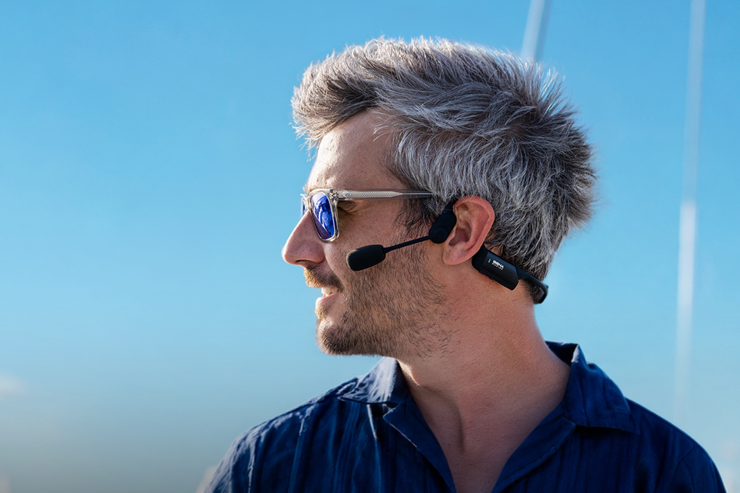
The “Quiet Revolution”: What First-Time Skippers Notice About Modern Intercoms

14 May 2026
-
Connected Cycling : Sena Brings Advanced Communication to Fahrrad Essen

15 April 2026
-
Sena at Lagoon Exclusive Days & Excess Factory Tour: Redefining Onboard Communication
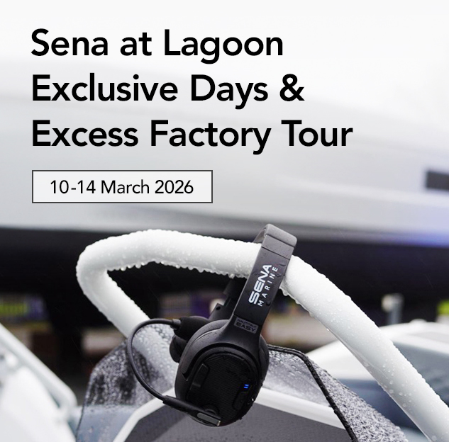
15 April 2026
-
Sena BiKom 20 Wins at the German Design Awards 2026
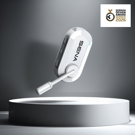
4 March 2026
-
Smart Helmets and Intercoms: The New Language of Cycling

12 February 2026
-
How Seamless Communication Changes Everyday Life Onboard
12 February 2026
-
5 Different Types of Cyclists — and How They Use Intercoms on the Bicycle

19 January 2026
-
5 Different Types of Sailors — and How They Use Intercoms at Sea
19 January 2026
-
Noise-cancelling Marine Tech Explained: How Intercoms Cut Through Wind and Engine Roar

12 December 2025
-
Inside the Smart Helmet: The Tech for Modern Cycling

12 December 2025
-
Marine Communication: Why You’ve Been Using the Wrong Tool Onboard

16 October 2025